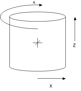
1.0 Coordinates
All coordinates are in a cylindrical polar scheme relative to an immediate parent.
- A = Rotation about a vertical axis in radians
- X = Distance from a vertical axis in inches
- Z = Position along the vertical axis, positive is up
2.0 Loads Applied to the Pole
Every component on the pole (and the pole itself) contributes loads to the pole in a number of axes and as a result of a number of contributory sources. There is, of course, a high degree of variability in the fine determination of these forces for each element type and each load source, but as a very general thing we can divide the forces thusly.
- Loads imparted by the weight of an element
- Loads imparted by the tension in an element as installed
- Loads imparted by the interaction of an element with wind
And we can then say for each of these loads there is a result that can be described in the following categories.
- Horizontal force at some given height (or range of heights) is applied (and by extension bending force may be applied)
- Vertical force may be applied along the central axis of the pole
- Torqueing force may occur along the shaft of the pole
- Offset bending may occur perpendicular to the shaft of the pole
In O-Calc® Pro these forces are collected and represented for each element by a collection of one or more instances of a representative structure known as the ForceSummary.
- /// <summary>
- /// Holds the forces acting at a particular height caused by, or offsetting, a
- /// particular PPLLement
- /// </summary>
- public class ForceSummary
- {
- /// <summary>
- /// Height above the groundline in inches
- /// </summary>
- public double cHeightOfForceApplicationAboveGLinInches = double.NaN;
- public double cHeightOfActualForceAboveGLinInches = double.NaN;
- public LoadComponent cWindLoadComponent = new LoadComponent(); //for a given wind angle
- public LoadComponent cTensionLoadComponent = new LoadComponent(); //force form tension
- public LoadComponent cGravityLoadComponent = new LoadComponent(); //force from gravity
- public BendingComponent cOffsetBendingLoadComponent = new BendingComponent();
- /// <summary>
- /// if the element exerts a secondary force (the arm of a sidewalk guy for example)
- /// its forces are placed here. If there is no secondary force then the value
- /// is null.
- /// </summary>
- public ForceSummary cSecondaryForce = null;
- public bool cIsSecondaryForce = false;
- /// <summary>
- /// The PPLElement generating this force summary.
- /// </summary>
- public PPLElement cElement = null;
Each if the components are then further represented as a LoadComponent or a BendingComponent as follows:
- /// <summary>
- /// Teh LoadComponent class is an atomic encapsulation of the vector
- /// bending forces at a single point as exerted by a single
- /// source. Operators for combining load components are provided.
- /// </summary>
- public class LoadComponent
- {
- //all force values are in pounds by convention
- public double cForceAxisA = 0;
- public double cForceAxisB = 0;
- private double cFactorApplied = double.NaN;
- public double cForceVertical = 0;
- private double cFactorAppliedVertical = double.NaN;
- public double cKz = double.NaN;
- public double cGrf = double.NaN;
- public class BendingComponent
- {
- //all bending values are in ft-lbs by convention
- public double cBendingLoadAxisA = 0;
- public double cBendingLoadAxisB = 0;
- private double cFactorApplied = double.NaN;
- private double cBendingLoadVerticalTorsion = 0;
- private double cFactorAppliedTorsional = double.NaN;
It is important to note that each load and bending component encodes any additional information required to determine both the overloaded and the raw forces present. In addition the Kz and gust response factors (in the event that this is a wind derived load) are retained.
Were these simple vector forces this would not be required. However, the fact that these forces are calculated cognizant of the fact that this is a pole load analysis system requires these additional values be calculated and maintained.
Decomposition of Forces and Reactions
Throughout O-Calc Pro the representation of forces and of reactions is handled in a decomposed form (see the force vector representations above). This means that forces and reactions in 3D space can be more conveniently visualized and processed in two planar surfaces. These surfaces represent Northings and Eastings when data is transferred between engineering and GIS units, but within O-Calc itself they are referred to as arbitrary axis A and axis B.
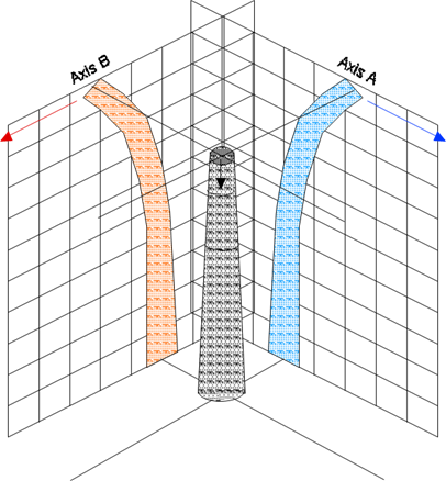
Throughout the remainder of this document it is the convention that when concepts such as deformation are discussed as if in a single plane it is to be assumed that in fact all operations occur in this decomposed form and are understood to be occurring simultaneously in each axis appropriately.
3.0 General Forms of Load Equations
Each element is responsible for calculating its own reaction to conditions and for populating its own force summary. Towards this end every class derived from PPLElement implements the method BuildForceSummary as well as a helper method ProjectedWindArea.
A detailed description of the algorithm for each element type is beyond the scope and intent of this document. Instead this is a general discussion of a selected set of general equations used throughout this process.
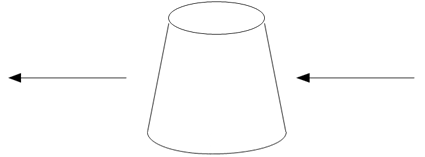
Wind on Cylindrical or Curved Surfaces
The simplest case is the effect of wind on a round or curved surface (transformer cans, etc). In these cases the force F is simply the projected wind area multiplied by the wind force expressed as a vector in the direction of the wind.
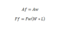
Where
- Af = Angle of resultant force in the horizontal plane
- Aw = Angle of the wind in the horizontal plane
- Ff = Magnitude of resultant force vector
- Fw = Wind pressure
- W = Width of exposed area
- L = Length of exposed area
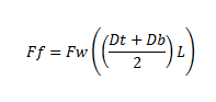
In the case of individual pole segments there is a very slight change in that the exposed area of a pole segment is a conic section not a cylinder. Therefore the pole segment uses the area of a frustum.
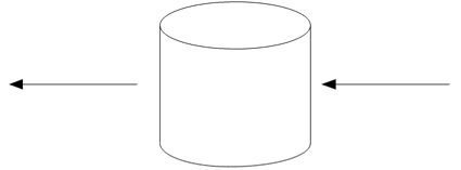
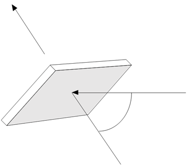
Wind on Planar Surfaces
The effect of wind on planar surfaces is only slightly more complicated. As a general proposition wind on a planar surface generates a force perpendicular to the surface of the plane with a magnitude that is the cosine of the difference between a ray perpendicular to the face and the actual wind angle. This is done in three dimensions so there is the potential for up-force or down-force as well as in the horizontal plane.
Wind on Spans and Other Cables
The case of wind on cables is similar in some respects to the force of wind on a plane in that the force exerted will be perpendicular to the span angle rather than in the direction that the wind is blowing. Similarly the magnitude is a function of the relative angle formed by the wind angle and the span angle.
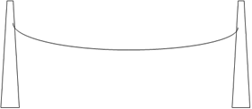
Additional consideration must be given to the fact that unlike almost all other pole mounted equipment the spans and guys are supported on two ends. As a result they share the load they impart between two different elements. In the case of a level span it is sufficient to simply split the load equally between the two supports. For cases of an inclined span you need to determine the minima point and apportion the load accordingly (depending on the wind angle you will also need to adjust the vertical component). This is handled using the catenary class described elsewhere.
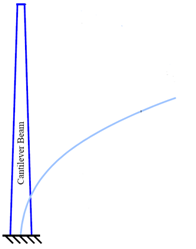
4.0 Deflection and Reaction of a Tapered Cantilever
When calculating the results of the application of the forces previously described we need a model of the primary structure against which all of these forces will be applied. In the case of O-Calc® Pro the structure used is a tapered cantilevered beam.
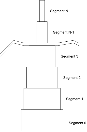
Application of Loads to Beam
In O-Calc® Pro the problem of modeling the deflection in the tapered pole is handled through Mesh Free Finite Element Modeling of the pole. The pole is segmented into a large number of non-tapered elements. Then modeling the loads in those segments and propagating the loads (and by extension the deflection) through the pole using an appropriate transfer matrix for the load type being applied.
In each segment there is some application of each load that causes a deformation.
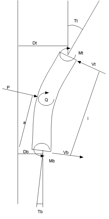
P = Point load
Q = Offset moment load
p = Distributed load
a = Height of application of load in segment
E = Modulus of Elasticity
I = Area moment of inertia of segment
V = Shear force at end (t = tip, b = base)
M = Moment at end (t = tip, b = base)
T = Slope relative to vertical at end (t = tip, b = base)
D = Displacement from vertical at end (t = tip, b = base)
Below are the matrices for each load type:
Point Load Transfer Matrix
![]()
Offset Moment Transfer Matrix
![]()
Distributed Load Transfer Matrix
![]()
To determine the actual deformation of the entire pole we need to solve the entire system for the set of applied forces such that D at the base of the pole is 0 and M at the tip of the pole is 0.
5.0 Elongation of a Wire Rope
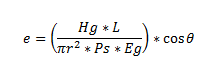
The guy wires are subject to elongation as forces are applied to the guyed structure. In order to calculate the reaction of the structure as a whole to the application of those forces we must model the reaction of the guy wires. This is done as follows:
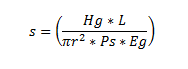
Where
- L = The length of the elastic portion of the wire rope
- r = The radius of the wire rope from outer bedded strand to outer bedded strand
- Ps = The percent solid of the wire rope as a ratio of the rope material compared to gaps
- Eg = Modulus of elasticity (effective) of the aggregate material
- Hg = Total tension
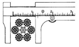
Correct Measurement
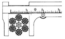
Incorrect Measurement
If we define the ” as the effective declination of the guy relative to horizontal (see effective declination for sidewalk guy) we can then say that the horizontal component of the total elongation of the wire rope would be:
Then at stasis we can determine the horizontal force being supplied by a guy wire (and by implication the amount of force being supplied by the pole itself) because at height h:
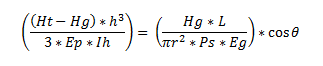
Since we know everything but Hg we can solve this quite simply and thus calculate the guyed system’s reaction to the load or loads.
6.0 Static Catenary Calculations
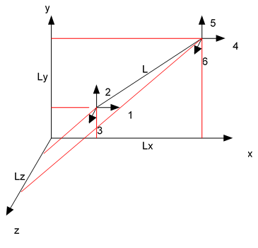
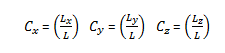
The guying reaction is determined by performing the deflection operation described in the previous section for all forces except the guying forces. Each of the guys is modeled as a classic truss member whose tension / elastic elongation is determined using the stiffness matrix as follows (the pretension is T0, the anchor end is r1,r2,r3 and pole attachment point end is r4,r5,r6 ):
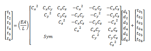
Obviously for the case of a fixed anchor (which our guys are in this system) we can simplify this considerably as follows:
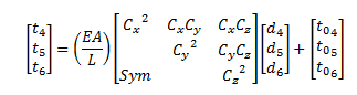
So that for any iteration we can look at the deflection in the beam previously described and determine that for that iteration the tension in the guys would be:
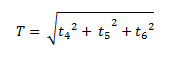
Through successive application we reach equilibrium where the value of T in each guy becomes stabilized.
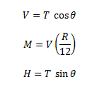
Application of T to the reset pole each cycle includes both the tension and the offset moment of each guy.
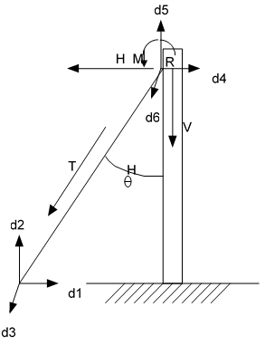
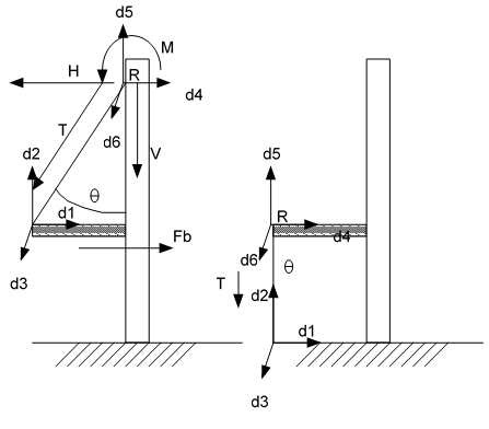
Down Guy, Head Guy, Span Guy and Pushbrace
In the special case of a sidewalk guy the system is modeled as two separate guys. Note that the guy arm itself applies only shear load into the pole since it is treated as a gimbaled structure.
It is important to note that limits on the change in T for any guy are artificially introduced based on the type of guy wire. Cables are not permitted to fall below 0 or above their breaking strength x 10. Pushbraces are permitted to range between negative breaking strength x 10 and breaking strength x 10. In this way we can be assured that the system will always drive to a solution and will never oscillate indefinitely.
7.0 Static Catenary Calculations
When working with the spans it is extremely useful to have a function capable of the complex job of working with the catenaries. This catenary class is used in many locations throughout O-Calc® Pro. The catenary class performs calculations and represents the span / catenary as follows:
Where
- D = Sag
- h = Elevation difference
- S = Span length
- H = Horizontal tension
- w = Weight of cable per unit length
- Xl = Distance from left support to minima
- Xr = Distance from right support to minima
- L = Linear cable length
- Dl = Drop from left support to minima
- Dr = Drop from right support to minima
- Tl = Tension in cable at left support
- Tr = Tension in cable at right support
- Tm = Tension in cable at minima
So we can calculate D as follows (and we can re-arrange to solve for other values):
Other utility functions in this class solve for:
8.0 Elastic Catenary Calculations
Obviously the equations in section 6.0 are for an inelastic catenary (chain). In O-Calc® Pro the problem of modeling the elastic nature of a cable catenary is handled through the re-application of the truss element discussed in section 6.0 and merging it with the catenary solver library described in section 7.0. In the same way that a tapered beam is modeled by combining a sufficiently large number of non tapered cylinders (or n-gons in the case of steel and concrete structures) a catenary form can be successfully modeled by combining a similarly large number of truss elements.
We can then use the same iteration engine and “HasConverged” boolean getter that supported guying calculations to support final tension / sag analysis.