Among the many tools included in O-Calc Pro is the option to utilize information collected with an IKE device. This article outlines how to utilize an IKE 3 device to collect data, and use that data to model a pole within the O-Calc Pro desktop software. The process for data collected from an IKE 4 is similar to O-Calc LE, in that it requires a configuration file be set up by the customer. Contact IKE for information on the IKE 4 process.
The first step is to ensure that the IKE Pole Screening Tool is enabled from the plugins list. To verify this, navigate to Options>>Manage Plugins…
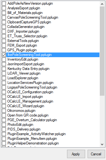
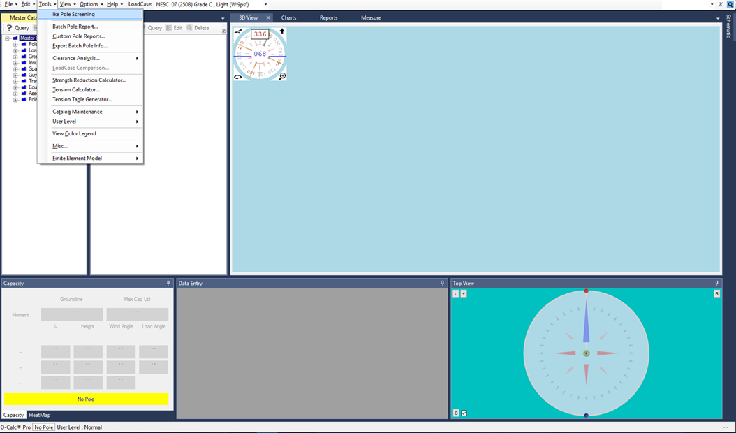
Once this plugin is selected, hit Apply. This will prompt you to restart the O-Calc Pro applications – select Yes. If the program does not restart automatically, make sure that it has closed and reopen it. Now you should see the Ike Pole Screening Tool listed under the Tools drop down along the top of the window.
When the Ike Pole Screening tool is selected, a window opens. Initially this window may appear to be blank, and an error message may indicate that a config file needs to be selected. Just proceed if this message appears.
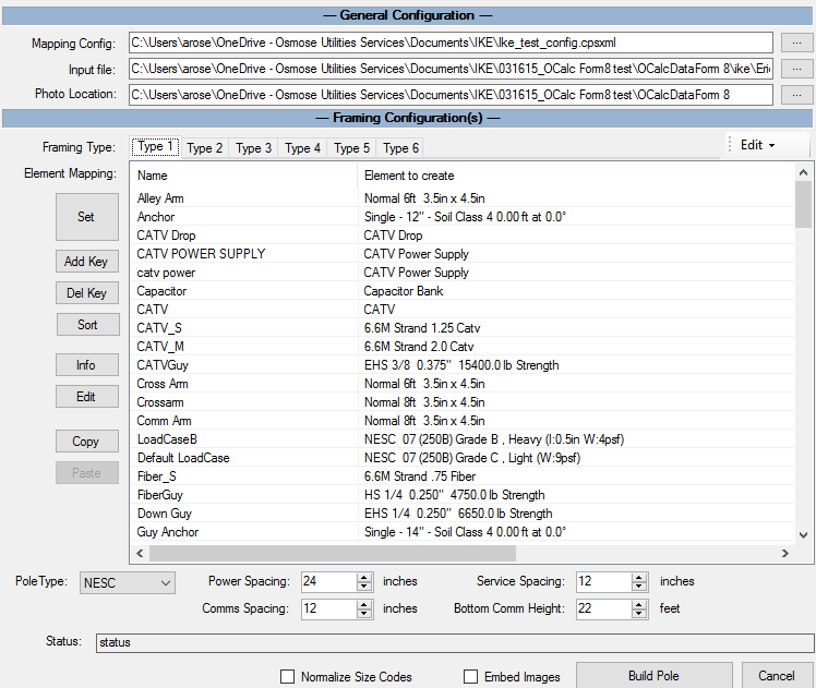
This is what a populated window looks like – this window shows a config file that is selected, an input .ike file, and a location for photos to be associated with a .ike file. Below is a breakdown of what each section of this form requires.
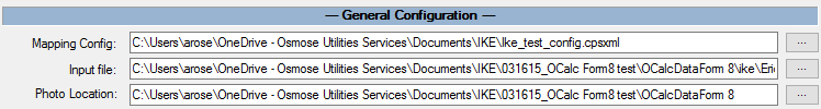
The top part of this window asks for the locations of three items – the config file, the input file, and the photo location. The Mapping Config file is responsible for matching components from the Ike device to a matching component from the input file. An Ike_Test_Config file that can be requested, and then modified by a user. This is the suggested method to be used, as creating a new config file is not supported.
The input file is essentially the file of information collected on the Ike 3 device. In the Ike Desktop application, it is possible to create a data collection form. If you intend to bring data into O-Calc, you must use a specific form for data collection – This is called the OCalcDataForm8. This file should be provided by IKE by request. This form can be opened and modified in the Ike desktop application, and loaded onto the Ike 3 device prior to data collection. Then, the .ike file that is created using this form, can be selected as the Input File in this part of the window.
The last item, the photo location, also has to be set. **Note, that when setting a photo location, the location should not be the images folder itself, but one folder up**. This location should be set to the folder that contains the Images folder, not the images folder itself. This destination knows to look for a folder called “Images”, so it must be set one folder location up in the hierarchy – it should not be set to the images folder itself.
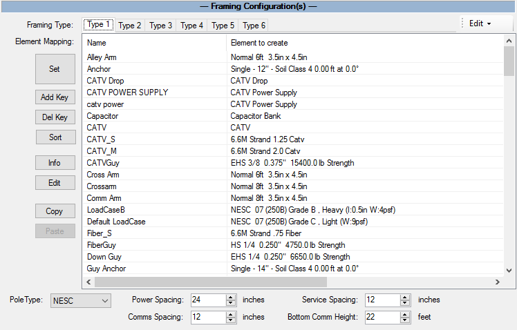
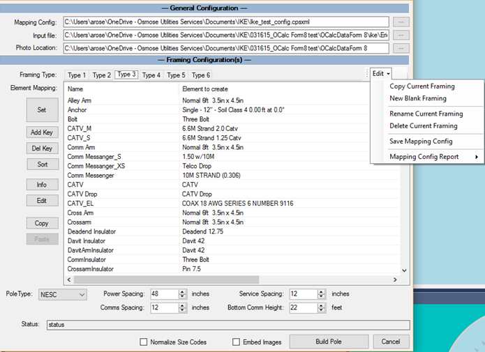
The rest of this window displays the matching information contained in the Mapping Config File. The Ike Test Config file available for download, contains 6 types of framing. This corresponds to the “Type 1”, “Type 2”, etc. tabs next to the “Framing Type:” section. Different Framing Types can be created for different scenarios. The attributes that can be modified for different framings are the attributes along the bottom of this window, pictured below:


These images show the framing type attributes for types 1, 2, and 3 in the Ike Tes Config file. Framing types can be added, deleted, renamed, or modified using the Edit drop down menu to the right of the tabs.
Each framing type has the same elements included; that is to say that the list of items being mapped from the .ike file to an element in O-Calc is the same for all framing types. As you will see in the Ike Test Config file, there are quite a few elements included.
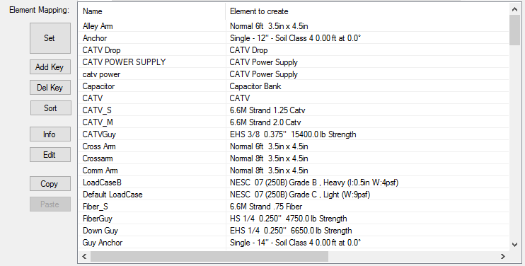
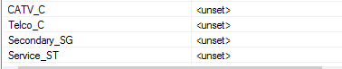
Pictured above is the list of items and their associated “matches” in the Ike Test Config file. This list can be modified by adding new items to the “Name” column by using the Add Key button. When a new item is added, it appears under the “Name” Column, with it’s match in the “Element to create” column being <unset>.
To set the match for that item, select the Set button. This will open a window which allows the user to choose an item from their Master and User Catalogs, to “match” to that item.

An item can be selected, and then OK can be pressed, which will set a newly created item in the “Name” column, to map to the selected item in the “Element to Create” column.


Items can also be removed using the Del Key button.
Other options in this area are Info, Edit, Copy, and Paste. Selecting an item from the list and pressing Info, will display attribute information for the element that is being created for an item. Selecting Edit will also display that information, and allow a user to modify this information by adjusting things like physical dimensions, span length and type, etc. Selecting Copy while an item is selected will copy the “Element to create” item, and then selecting another item and pressing Paste will change the element that it maps to, to be the copied item.
Now, once all of these parameters are set/established, a user is able to build the pole based on the information in the selected .ike file.
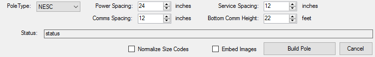
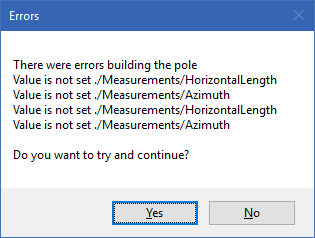
A user can choose a Pole Type, which sets the type of loadcase applied. There is also the option to Embed Images into the .pplx file that is created. Once a user presses Build Pole, the .ike file is read, matching items collected to the list that is populated. Each item is “Matched” to the O-Calc “element to create”. If something is not found that does not have a match, a warning pops up that may look something like this:
A user can proceed, and modify the O-Calc structure once it is built. Also, if changed have been made to the Ike Test Config file, a user will be asked whether or not to save those changes. As the original file is overwritten, it is advised that a backup copy be stored on the user’s PC.
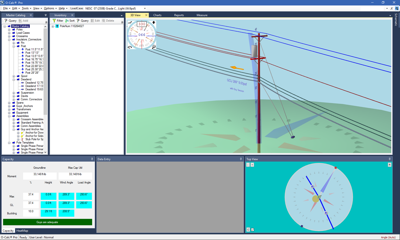
When finished reading the files, a pole will be built.