The Clearance analysis tool provides the user with a way to assess for potential clearance violations when adding spans and equipment, or when setting a new pole. The Clearance Analysis options can be found under Tools > Clearance Analysis… in O-Calc Pro. From this list are several options, including Clearances and Violations, Show Clearance Rules, Edit Clearance Rules, and Clearance Rules and Maintenance.
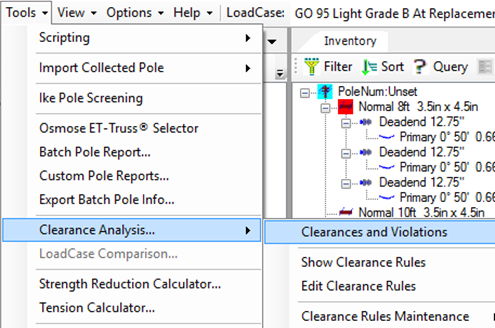
Clearances and Violations – this option allows the user to check for violations of the clearance rules once they have been set – prior to setting the rules and if there are no violations, the user will only see a pop-up stating that
Show Clearance Rules – this option opens a list of all the rules that have been established, with options to print, email, and save a copy of the list. This is useful for documentation regarding what the clearance rules on a project are.
Edit Clearance Rules – this option opens a window where the user can edit clearance rules. From this window, a user can add rules and violations, clearance groups, and types of violation structures.
Clearance Rules Maintenance – this option has two additional choices – import or Export clearance rules. This allows for an organization or person to take clearance rules they have created, and export them to their working group. Additionally, participants who receive a clearance rules file (file with extension .crx) can import those rules without having to re-create them from scratch.
Process
Below is a listing of the steps that must be undertaken to have the clearance analysis tool work as expected.
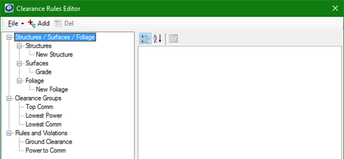
Set up Clearance Rules – by selecting ‘edit clearance rules’, a window will open where a user can begin creating clearance rules. This window will appear:
The main categories for adding rules are listed in the tree in the image above.
- Structures/Surfaces/Foliage – adding items like buildings, slopes and trees to these different subgroups allows the user to determine whether any of these components violate a clearance rule. This section can be used to create some default items. By highlighting the “structures” heading and selecting the Add button, attributes can be entered for a type of structure. The same can be done for surfaces and foliage, each with different attributes that can be entered.
- Clearance Groups – these groups are used to identify what each item on the pole is – these need to be created and any number of groups can be added by highlighting the “clearance groups” heading and selecting the Add button. For example, one list of groups might be ‘Power, Comm, and equipment’. One of these groups will be added to each item in the inventory list later on – at this stage we are just creating a list of options.
- Rules and violations – this is where the actual rules are entered by the user. By highlighting the “rules and violations” heading and selecting the Add Button, the user can input a clearance in ft, a name for the rule, set the targets that the rule applies to, and set a severity level for a violation of this rule. A good example is a rule called “Ground Clearance”, where a user can set a minimum distance that must exist between the lowest item on the pole and the ground. This could be an example of a high severity violation.
Once you’ve added all the rules, go to File > Save to commit the rules.
Assign Clearance Groups to Components – now that we’ve created groups, we need to place them onto items in our inventory list before running a check. The easiest way to do this is to select an item, say a span, and right Click > Add Other > Clearance which will open up a “Create New Clearance” Window.
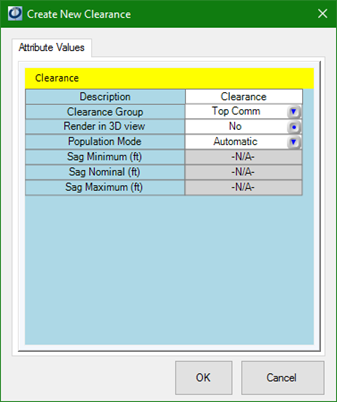
In this window, select the clearance group that best fits the item selected.
It is also possible to adjust the sag that is considered when this item is a span; this is what population mode refers to – the method used to populate sag values. For instance, leaving population mode set to ‘Automatic’ assumes a sag value, while changing the mode to “manual” will allow the user to enter values for Sag Min, Sag Nom, and Sag max.
Once all the attribute are as you would like them, select Ok.
Continue this process until all items in the inventory list have been assigned to a clearance group for the analysis.
Create Vectors to run the analysis within– Once a clearance group has been assigned to an item or items, the next step essentially tells O-Calc where to look for these violations. This can be done by opening the window found under Tools > Clearance Analysis > Clearances and Violations – this is the window where we can begin to enter our vectors.
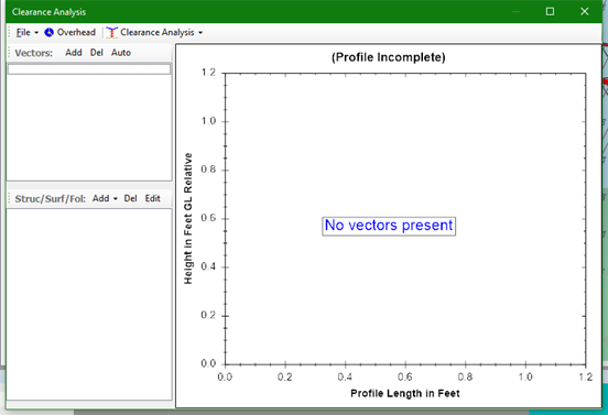
- Near the “Vectors:” header, select the Add button to create a new vector. In the pop-up, enter an angle that you would like O-Calc to check for validations. Ideally you will create a vector for each angle where spans, equipment, or other pole attachments can be found as these are the areas we’d want to check.
- Once a vector is created, it will appear in a list below the “Vectors:” header – all added vectors will appear in this list.
- Alternatively, the Auto button will create vectors for all span angles.
- Next, it will be possible to add potential violators of the clearance rules. These can be added under the “Struc/Surf/Fol:” header, also using the Add button.
- Any number of structures, types of foliage, and surfaces can be added to any vector to run the clearance analysis; once added, these items will be drawn in the profile graph within this window, to depict a simplified view of all items as they are in the field
- Once completed making additions, this window can be closed.
Run the Clearance Analysis Report– with the previous steps performed, it is possible to run the report “Clearance Report” from the Reports tab in O-Calc. If there are any violations of the rules, there will be a report generated which includes a listing of the violations, where they occur, and what severity they are. If there are no violations, the report will indicate that none were found.
Below is a detailed explanation of various components of the clearance analysis report.
Clearance Analysis Report
The clearance analysis report can only be created if a clearance analysis profile and associated clearance analysis rules have been created and established. For additional instructions on how to do this, see pages 200-213 in the O-Calc Pro user guide. Running this report will flag any violations to the established clearance rules and indicate those errors to the user.
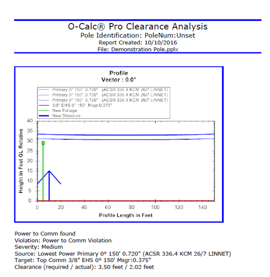
Figure 9. Clearance Analysis Report
Lines 1, 2, and 3: Indicates that an error was found, and what type and severity.
Line 4: Source of the Error and what type of material is causing it. Determined by severity assigned to that particular item – lower severity is considered the source.
Line 5: Target of the Error and what type of material is causing it. Determined by severity assigned to that particular item – higher severity is considered the target.
Line 6: Displays the rule and what the actual value is.
Recent Comments