Crossarm Analysis
The detailed crossarm analysis report indicates to the user whether one or more crossarms on the pole are adequate or not. This can be helpful when a crossarm is flagged in red in the inventory window – the red coloring on the icon usually indicates that the crossarm is failing or inadequate in some way. The report can be useful in identifying what attributes of the crossarm are inadequate or what loads on the crossarm are causing it to fail.
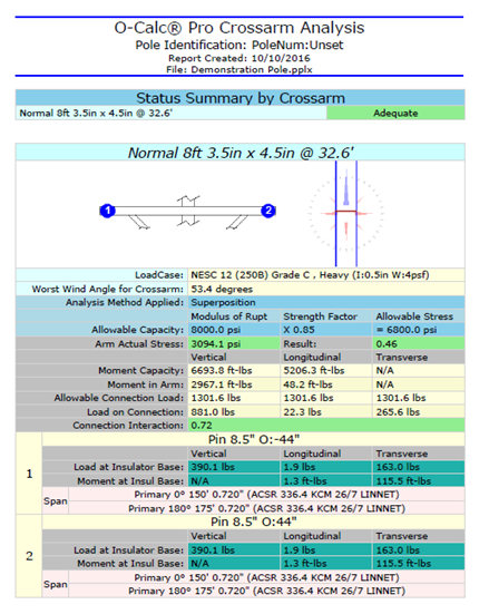
Beneath the header information of this report is the Status Summary by Crossarm section, which lists all crossarm’s included on a pole. In the example below, one arm is shown with a status of adequate. In cases where there is more than one crossarm on a pole, there will be a list of crossarms with a status of either adequate or inadequate.

Figure 1. Crossarm Analysis Report
The images on this report show the crossarm and attachment points (left) and an overhead view (right).

This section of the crossarm analysis report shows what values are being used when running the calculation. The method being applied for the analysis of the crossarm is shown, as well as values for the allowable capacity, the strength factor being used, and the allowable stress. The “Superposition” method is one of three methods that can be used when the Capacity Method of the crossarm set to “Automatic”. This can be done in the data entry window, under the filter “Analysis”. Additionally, “Automatic” can be used with the Analysis Methods “Interaction” or “Worst Axis”. If the Capacity Method is set to “Manual”, values must be set by the user in the data entry window for the calculation and the Analysis method can either be “Interaction” or “Worst Axis”.

This next section shows how much of the allowable stress is being applied to the crossarm, and how much of the allowable stress is being utilized. In this example, 46%, or 0.46 of the crossarm’s allowable stress is being applied.
Actual Arm Stress – amount of bending stress applied to the arm by the moments on the arm
Moment Capacity – indicates the maximum allowable moment that can be applied to the arm
Moment in Arm – indicates the total moment being applied to the arm
Allowable Connection Load – amount of load that may be applied at the connection point, or insulator
Load on Connection – actual applied load at the connection point, or insulator
These values are given in relation to Vertical, Longitudinal, and Transverse loads.
At the bottom of this section, we can see the connection interaction value,

This image shows the crossarm being analyzed in this report, with numbered nodes to indicate where an insulator is attached, and thus where forces are being applied to the crossarm that are consuming some of the moment capacity of the arm.

This window provides data corresponding to one of the numbered nodes. It indicates the type of attachment and its offset value, as well as this insulator’s individual vertical, longitudinal and transverse loads at the base of the insulator. There is also a list of what is attached to this insulator.
Crossarm Summary
For less detail about the crossarms on a pole, a user can view the crossarm summary report. This provides a brief listing of crossarms attached to a pole.

This report also provides information about each individual insulator on a crossarm, as well as information regarding the transverse, longitudinal and vertical loads.
Total force is given as a worst-case total.
Recent Comments