The DMT, or Digital Measurement Technology, process in O-Calc Pro allows a user to obtain information from a photo of a pole that was taken with a CVT, or a Calibrated Visual Target. This technology allows a user to obtain attachment heights, span diameters, and other information. However, if a photo is taken without a CVT, there are now alternative methods that can be used to obtain information.
One method is the use of a Control Point, or a point with a known height, on a photo that does not have a CVT or range pole in the photo.
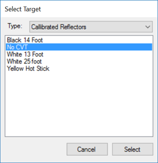
To use this method, begin modeling a pole and bring in your photo. Then, set your target type to “No CVT” mode. In this mode, O-Calc assumes that the height of your modeled pole, and the height of the pole in your image, are the same. This makes it essential to model a pole accurately in your inventory/3D View.
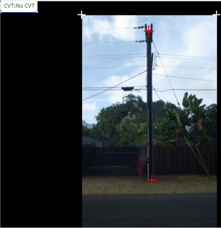
Next, while in the “Calibrate” mode, you will calibrate by identifying the bottom or the pole (where it meets the ground) and the top of the pole. After selecting these two points, O-Calc exits “Calibrate” mode and switches to “Height” mode, as it is not expecting any more targets.
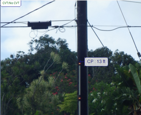
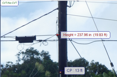
At this stage, it is possible to set a control point, to improve the accuracy of measurements taken from the image. A control point as a point on the pole where the height is known. This could be obtained from measuring the attachment point of the lowest communication attachment in the field, or using a hot stick, or some other item with a known height. In the picture below, I used a control point at the top of the CVT Stick in the photo, since I know the value is 13 ft. Again, this could be any point along the pole, and a CVT Stick is not required to utilize this process.
A control point can be set by holding down the CTRL key, and clicking a point on the pole while in “Height” mode.
Note: Ensure that nothing is selected in your inventory or 3D View – having an item selected will prevent this option from displaying.
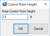
Once a control point is entered, press OK. This will display the value on your image.
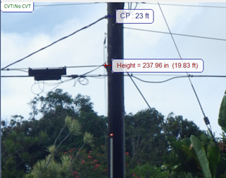
With the control point in place, any height measurements taken near the control point become more accurate. However, only one control point can be active at a time. It is possible to set a new control point – none of the height modification you’ve already made will change when a new control point is set.
To remove a control point, right-click on it and select Delete. Then, set a new control point using the method described above.