The O-Calc Pro Master Catalog contains many items that can be modeled on a utility pole. However, not all items found in the field can be found in the catalog. For this reason, O-Calc Pro has the ability to model items as generic equipment using a blend of shapes with different attributes.
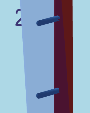
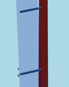
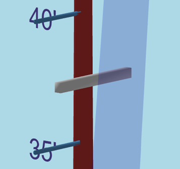
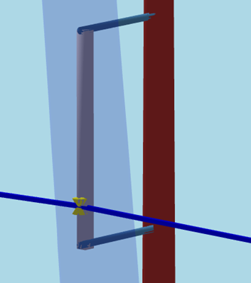
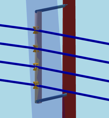
One common piece of equipment seen in the field is a spool rack – a rack that holds several spools away from the pole, keeping the secondary spans a certain distance off the pole. Below are some images that show this arrangement.


There are two ways that this arrangement can be modeled. This wiki page outlines both of those methods.
Method 1
The first method is to use generic equipment to essentially build the rack. Then, once finished, the spools are added directly to the pole, with the associated spans. Then, the spans are offset from the spools towards the end of the rack. It does look slightly peculiar, as the spools are still on the pole but the spans are not. However, it does calculate the loading correctly.
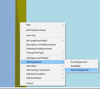
So, the first step would be to open a pole. Then, right-click on the pole and go to the “Add Element” option in the list – this list may also be divided into different categories, if that setting is enabled. You will want to select Add…Generic Equipment.
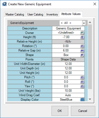
In the ‘Create New Generic Equipment’ window, select the ‘Attribute Values’ tab, and change to the ‘All’ filter. This will show you all of the attributes you can adjust for your generic equipment.
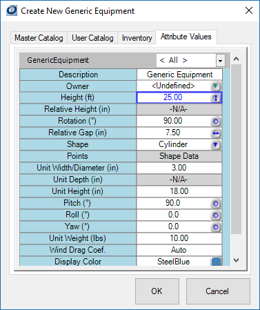
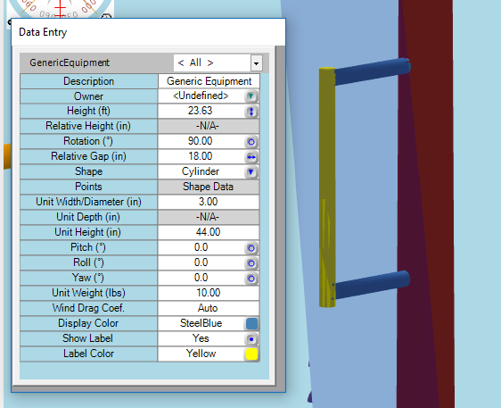
I am going to adjust my shape to a cylinder, enter my height, change my width and unit height, adjust my pitch, and set a relative gap and rotation. The values entered are shown below.
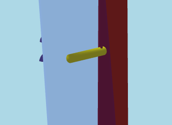
When finished, press “OK”. You will see the piece of generic equipment on the pole at the set height. To move the equipment into a new spot, simply adjust the height or rotation attributes.
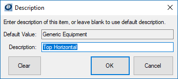
You will notice this equipment added to your inventory list. To change the name of this equipment to something more informative, right-click on the text in the inventory, and select the description option. Then you can enter a more appropriate name, like “Top Horizontal” for this piece of the spool rack.
To get the bottom part of the spool rack, simply copy the top horizontal piece. To copy, just drag and drop the item back to the pole. You can then adjust the installation height, and rename this piece to be “Bottom Horizontal”.
The last piece will be the vertical section that connects these two. Make another copy of the top horizontal piece. Set it’s installation height to be between the two other pieces, and rename it “vertical”. Then, in the data entry window for that section, adjust the pitch back to 0 and change your unit height so it touches both of the horizontal segments.
This completes the actual rack part of the spool rack. Next, we can add in the appropriate number of spools onto the pole, each a few inches apart from the others. With the spools in place, the spans can be added.
The last step is to offset the spans away from the pole. To do this, select all of the spans. This can be done by holding down the Ctrl key and clicking on each one in the inventory list. Then, in the data entry panel, you will see a column for each of the spans.
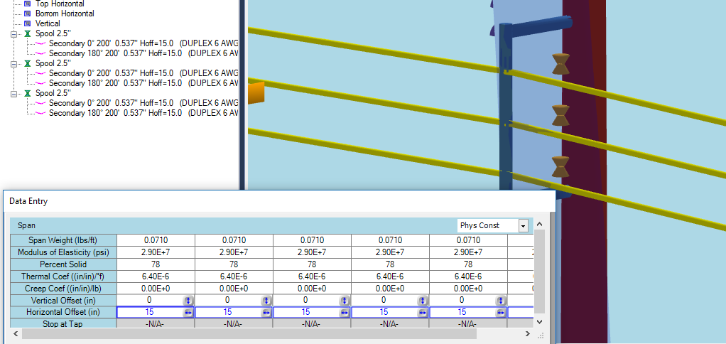
Again, the results look a little strange but the calculations are correct. This concludes the easier method for modeling a spool rack. We recommend saving the components of the spool rack into your user catalog for further use.
Method 2
The second method of modeling a spool rack relies more on crossarms than on generic equipment, and could be considered the more difficult method. This method requires creating a top and bottom segment from generic equipment, just like in method 1. However, these segments are the only two pieces of generic equipment. The third segment is actually a crossarm, rather than a third, vertical piece of generic equipment.
Again, begin with two horizontal pieces of generic equipment. Instructions for creating these are provided under Method 1. Then, once they are in place, add a crossarm to the pole between the two pieces. Any size crossarm will work, as it will be adjusted. Turn the bracing off, under the Brace Filter. Then, change the material to “Steel”, under the Material Filter.
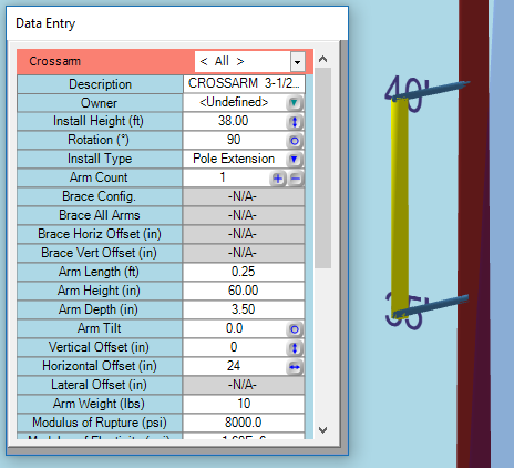
Next, go back to the standard filter, and set the Install Type Attribute to a “Pole Extension”, and rotate by 90°. Then, go to the dimensions tab, and adjust the arm length, arm height, and arm depth until the crossarm appears to be vertical. Lastly, go to the Physical Filter, and set the crossarm’s Horizontal Offset Attribute to 24, or whichever value corresponds to the length of the horizontal segments of generic equipment.
With the vertical segment in place, now the spool insulators can be added. Begin by taking one spool, and placing it on the crossarm. Once the first Spool is in place, add the required spans to it. Adjust the Install Height attribute to position the spool on the crossarm.
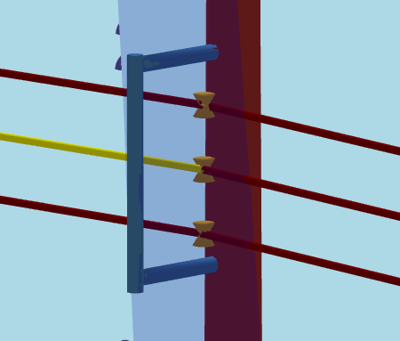
Copy the spool two or three more times, adjusting the Install Height Attribute for each new spool until they are the correct distance apart.
The spools shown in this image are about 1 foot apart. While this method is similar to Method 1, there are a few more steps required for the manipulation of the crossarm.