A pole top extension is designed to extend the height of the pole, generally through the use of a crossarm or additional attachment. This attachment elevates a span or piece of equipment above the existing height of the pole. Since this is a fairly common practice, a user can model a pole top extension in O-Calc Pro using one of the methods outlined below. To begin with, method one reviews how to model a wooden pole top extension with a double crossarm. The second method shows how to use generic equipment as a pole top extension, if desired.
Method 1
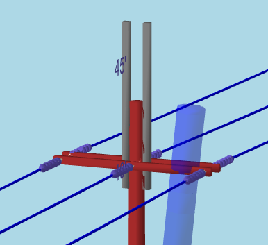
To add a pole top extension, begin my adding a crossarm to a pole. Set the height of this crossarm to the top of the pole, or Install Height = Tip if you wish to use the shortcut. Entering a height value of “Tip” will set the crossarm’s height to the very top of the pole. Below is an image of a pole, with the positioned crossarm.
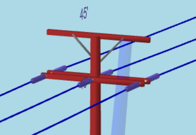
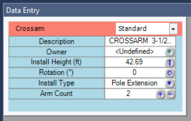
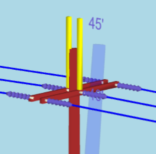
The crossarm used here is a ‘Normal 8ft 3.5in x 4.5in’ crossarm. Select the crossarm; in the Data Entry Window, change the Install Type attribute from ‘normal’ to ‘pole extension’. This will remove the braces for you. Next, if your pole top extension consists of two arms, set the Arm Count attribute to 2.
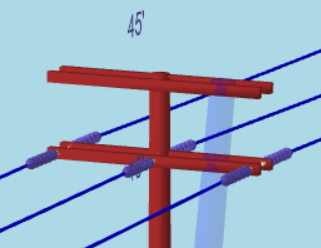
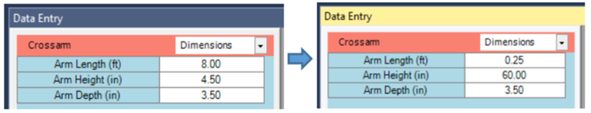
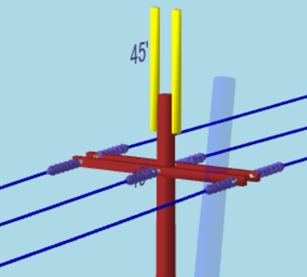
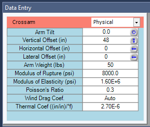
Next, change your filter in the Data Entry Window from ‘Standard’ to ‘Dimensions’. Here you can see the length, height, and depth of the crossarm. These attributes can be adjusted to make the crossarms appear to be vertical. While there is an ‘Arm Tilt’ option under the ‘Physical’ Filter, this option does not allow the user to rotate the arm more than 45°. So, adjusting its dimensions is the best approach to extend the arm vertically. Below are my original dimensions, followed by my new ones, and an image of the crossarm’s appearance after the change.
Additionally, if necessary this pole extension can be rotated. In the Data Entry Window, under by ‘Standard’ filter, I can set my rotation to any value I like. In this case, I can rotate it 90°. Additionally, the height of this pole to extension can be adjusted further, under the Height attribute. The Pole Top Extension can be moved to any height that does not exceed the top of the pole.
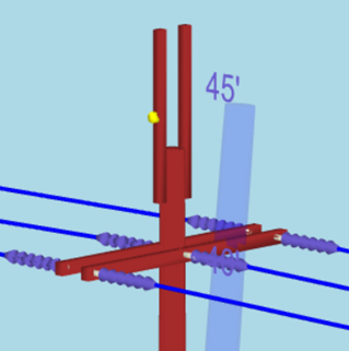
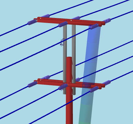
Once positioned, a user can add insulators to this crossarm. The insulators will be required to add spans or generic equipment to the pole extension. For instance, a single bolt can be added to the pole extension. It will be placed by default at the center height of the pole top extension. Adjusting the bolt’s Horizontal Offset attribute will move it from left to right, while the Install Height attribute can be adjusted to move the bolt vertically on the pole extension.
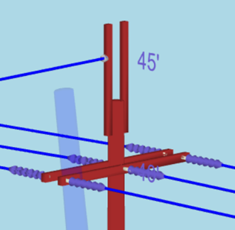
Once placed, spans or generic equipment can be added to the bolt to complete the model.
Method 2
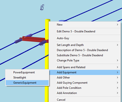
In addition to modeling pole top extensions with crossarms, they can alternatively be modeled with generic equipment. Starting with the same pole, we can add generic equipment directly onto the pole. Right-click on the pole, and in the Add Menu select Generic Equipment. This will open a window that allows you to edit the generic equipment’s properties.
In the ‘Create New Generic Equipment’ pop-up, go to the ‘Attribute Values’ tab, and set the filter to ‘All’.
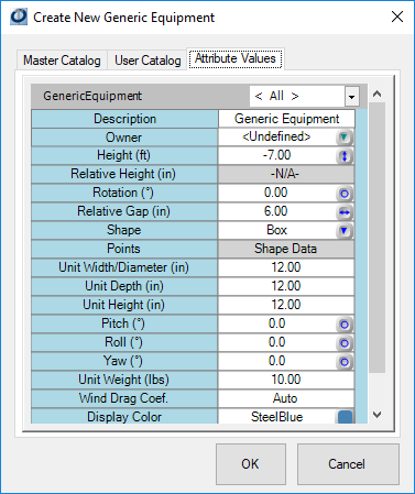
Here the user can adjust the parameters of the generic equipment. Position the window to be beside the pole in the 3D View, so that the edits can be seen as they are made. Begin by setting the Shape to be a Box and the Height to the ‘Tip’ of the pole. This will position the Generic equipment object at the top of the pole, so we can see edits as they are being made.
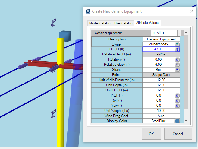
Next, we need this shape to look more like a crossarm. I can set Rotation to 270°, Unit Width/Diameter(in) to 3.5″, Unit Depth (in) to 4″ and Unit Height(in) to 96″. This will generate a piece of generic equipment that resembles a crossarm. To move the crossarm up, adjust the Height value. To position closer to the pole, set the Relative Gap(in) to 0″. Lastly the Display Color of the object may be changed, so it is more realistic looking. I’d choose grey, for a metal pole top extension.

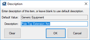
Once these changes are made, click “Ok”. In the Inventory, an item called ‘Generic Equipment” will be added. Right-click on this object and select “Description of…” to edit the description. Re-name it “Pole-top Extension Arm”.
Create a copy of this equipment – rotate it to 90°, or whichever rotation is 180° off the rotation of the first arm. Only do this if the pole top extension has two arms.
Once in place, additional items can be added. For instance, adding another crossarm. The crossarm must be placed on the pole. Then, in the data entry window under the “Physical” filter, the Vertical Offset can be adjusted to give the new crossarm the appearance of being attached to the pole top extension arms.
All attachments to generic equipment pole-top extensions must be added to the pole, and then moved using the vertical, horizontal, and lateral offset options; insulators, equipment, and generic equipment cannot be placed directly onto generic equipment.