The DMT Process refers to the use of the Digital Measurement Technology in O-Calc Pro. This technology typically requires a photograph of a pole be taken with a CVT, or Calibrated Visual Target, attached to the pole. This CVT is used in O-Calc to obtain height measurements for various attachments. With the release of O-Calc Pro 5.03, additional options became available for using the DMT features. This article outlines the use of a Range Survey Pole for obtaining height measurements, as an alternative to the CVT when obtaining a CVT is not possible.
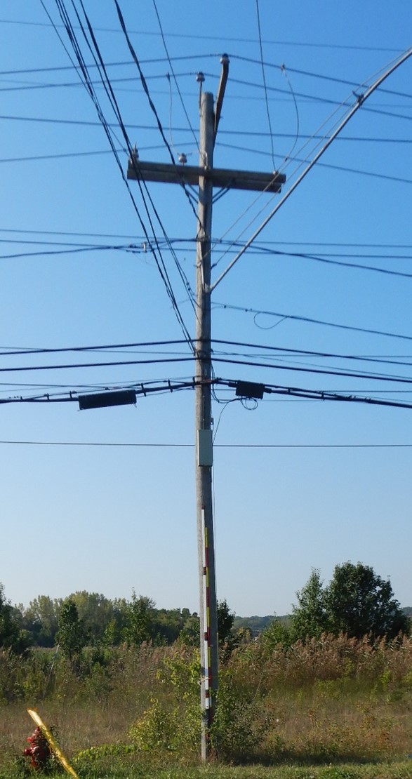
Range Survey Poles are available in several sizes and units. Typically, they are available in 4, 8, 12, 16, or 20 foot sizes. Additionally, meter sizes are also available. To begin, a photo must be taken with a range survey pole up against the utility pole. Below is an image that one might use. This image actually shows a CVT stick beside a range survey pole, but this is not necessary in the field.
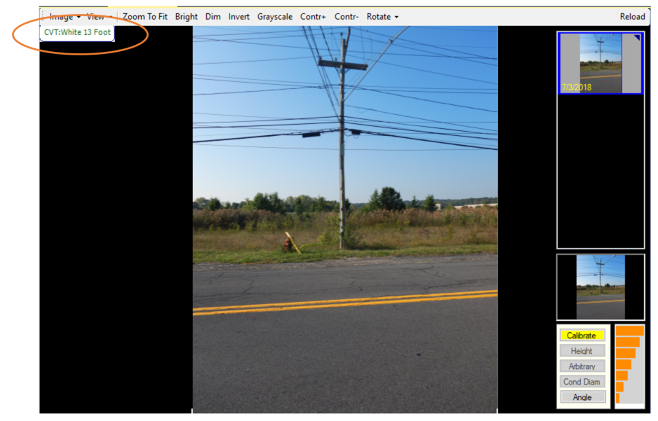
Once a photo is taken, bring the photo into O-Calc Pro using the options found under the Edit > Pole Images section in the main interface. Once selected, the pole image will be placed in the measure tab. Before beginning calibration, the target type needs to be set to match the range pole. In the measure tab, the upper-left hand corner shows the current target type.
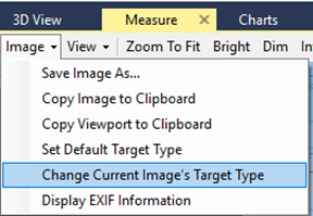
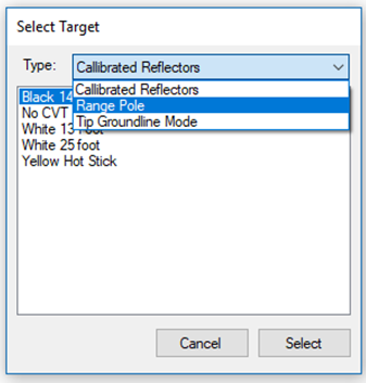
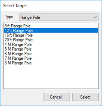
To change this target type, select the Image drop-down option in the measure tab ribbon, and select Change Current Image’s Target Type. This will open a selection window to choose a new target type. Under the Type drop down, select the Range Pole option. This will display a list of available range pole sizes. Select the size that matches the range pole being used in the pole image, and click “Select”.
This will change the target type displayed in the upper-left hand corner of the measure tab, to the newly selected target type.

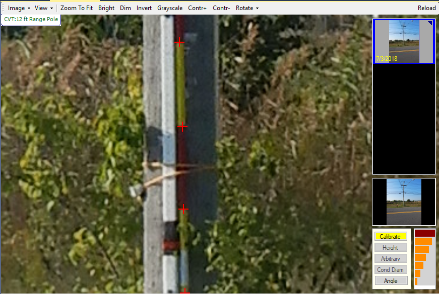
Now that the target type is correct, calibrating the image can be done. To calibrate with a range pole, simply click on each of the areas where the color changes from red to yellow, or yellow to red on the range survey pole. Begin at the bottom, and work your way up the pole. By selecting the correct range survey pole size, you are setting the expected number of clicks in the calibration step.
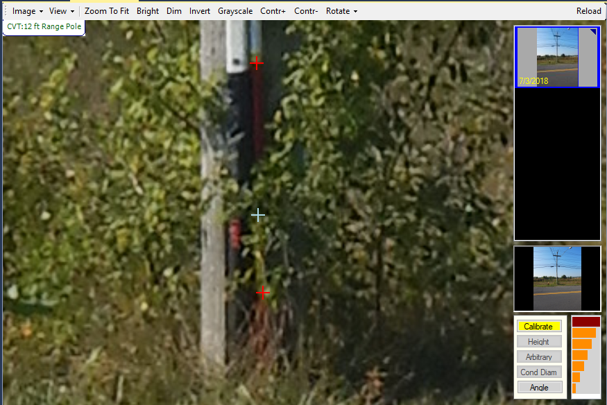
If any of the color-change points are obscured by something, like a shrub or a car, the calibration point can be skipped by holding down the shift key, and then left-clicking on the image approximately where you might expect the calibration point to be, if you could see it. You may skip a good amount of points, but this decreases the accuracy of your measurements. The skipped calibration points are marked with a white crosshair, instead of a red one.
Once all the expected calibration points have been selected, the Calibrate button is no longer highlighted, and height measurements can be taken using the same steps one would use when using a CVT.